Tips & Tricks
Claas Front axle drive shafts
Warning, danger to life!!!
In the first cut of the 2022 season, a steep slope had to be harvested. The machine was chopping downhill when, for no apparent reason, it suddenly picked up ground speed rapidly. The reflexive stepping on the brake pedal only caused the machine to yaw to the left, but there was no noticeable braking deceleration despite the all-wheel drive being switched on. As a last resort, the driver quickly turned the steering wheel to the left in order to bring the machine, which fortunately stopped despite the relatively high speed, to a halt across the slope. At the time in question, the tractor with trailer was to the right of the chopper, otherwise a collision would have happened here as well. The reason for this behavior: A broken right drive shaft on the front axle!
Therefore, the urgent advice to all owners of such a Claas axle is to check the drive shafts in your own interest with a "crack detection spray"!
All Mengele SF 6 and SF 7, Claas 690 to Jaguar 800 (Type 490), all Claas Dominator/ Mega and the Case "CF" machines are affected!
This list does not claim to be complete!

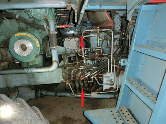
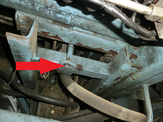
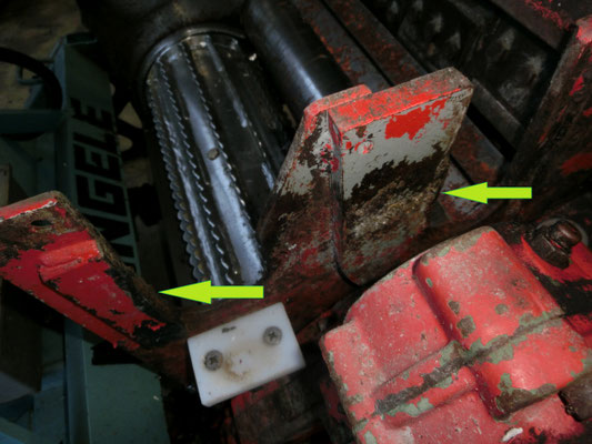
Control of hydrostatic pump series SF 6
A machine of the SF 6 series suddenly could no longer control the hydrostat correctly and could no longer stop completely. Fortunately, this happened in the field, but on public roads this could have fatal consequences!
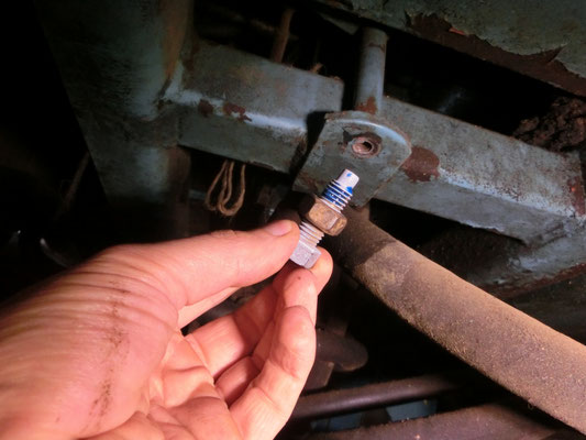
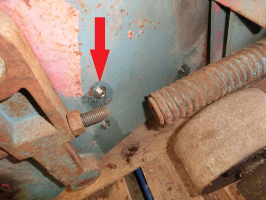
The cause: A hex-bolt fellt out of a reversing lever of the hydrostatic control, which is located behind the valve block within the main frame.
We urgently recommend that all SF 6 owners check these two bolts and secure them with Loctite!
The following pictures show which two bolts are involved:

Repair of panels for fan- and cutting-houses

It happens again and again that we come across fan and drum panels that have been "repaired" by some previous owner. The panel on the left is a classic example: From the outside it looks absolutely flawless. The "repair" is even so well done that it is not immediately recognizable as such (click on the picture).
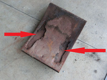
On the inside, all the horror comes to light: A metal sheet was simply welded over the worn-out original casing sheet from the outside. The original sheet metal was not cut out. The result: Razor-sharp metal plates gradually detach from the worn original metal plate, which then end up in the feed and then cut open the esophagus and stomach of your animals from the inside.
With such a cover plate you put your animals in danger!
Therefore, check all your drum and fan bases, such work has also been seen on fan housings!
This recommendation applies to forage harvesters of all types and manufacturers. We always have all panel plates in stock, these are available at short notice.
For third-party products, we have panels plates on request.
Additional driver strips on the corn header
Lubrication of bevel gears Mengele headers
The bevel gears for driving the individual intake chains are fitted with bearings that have to be lubricated once a year using lubricating nipples.
These grease nipples are very inconvenient to reach under the machine.
As an improvement, a lubricating bar was attached to the left side of the machine on this MG 43Z and lubricating lines were laid to the said lubricating points so that they can now be lubricated very easily from the outside.


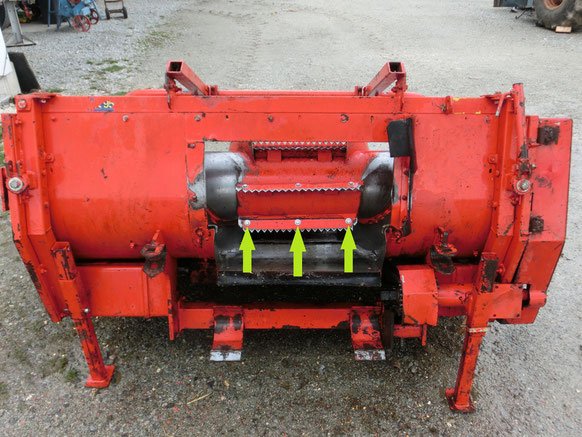
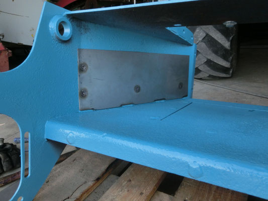
Wear plates cracker housing SF 6
In the cracker channel of the SF 6 series, there are no wear plates installed on the inside, which means that there is a considerable amount of repair work to be done in the event of advanced wear.
In order to avoid this effort from the outset, exchangeable metal sheets were attached into this channel, which can be easily changed if necessary.
The position of the upper fastening screws must be chosen well, so that they do not collide with the external tension springs of the upper crushing roller!


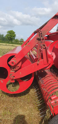
Optimized crop flow at PU 3000
In order to make the flow of forage from the pick-up to the chopping unit more constant, the corners of the outlet chute were smoothed out on this pick-up. The forage no longer has to change direction once by 90°, but only once by 30° and then by 60°. The result is a more even feeding of the chopper.


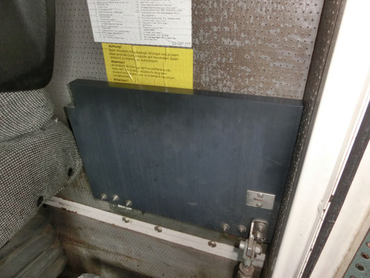
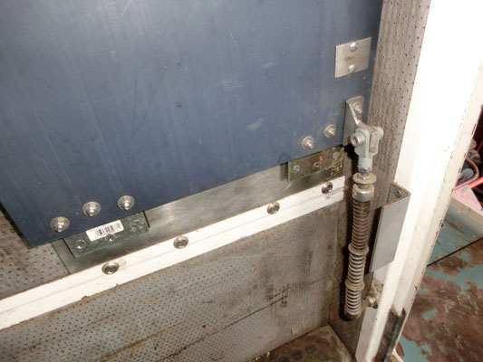
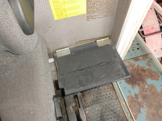
Passenger seat at SF 6
Here is an example of a relatively simple passenger seat that you can build yourself: A plastic plate was attached to the rear wall of the cabin using two sturdy hinges, which can be folded up using compression springs. A piece of flat iron attached to the door frame serves as a stop when folded down. Since the space in the cabin is relatively cramped at this point, the driver's seat was moved about 30mm to the right.


Filling quantities of air conditions

The specified values do not correspond to the official specification, but have nevertheless proven to be a good fit in practice.
SF 6 series: 1.4 kg
SF 7 series: 1.9 kg
R 134a is used as the refrigerant.
Guide rockers of intake auger MG 43Z
In the last version of the MG 43Z, i.e. with the ball-bearing augers, the position of the augers is stabilized using a simple steel bracket that is supported on the side wall. Since "iron rubs against iron" here, the wear is of course very severe. To minimize this, a simple grease nipple was inserted into the support brackets.
Please note: The grease nipple must point downwards, otherwise you will not be able to reach it with the grease gun if the protection-cover is installed!


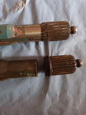
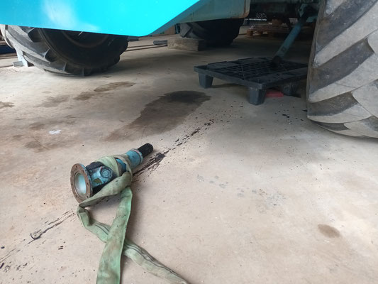
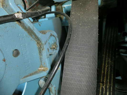
Cardan shafts for 4-wheel drive
By chance it was discovered that the wedge profile of a cardan shaft could only be moved with an extremely high expenditure of force.
The cause turned out to be moisture that had penetrated, which caused corrosion on the wedge profile despite the existing lubrication-film.
A wedge profile that does not move smoothly can cause very expensive repairs to the front axle output gear or the rear axle differential!
It is therefore recommended to unflange the cardan shafts of your machines on one side and to check the ease of movement of the wedge profile!
All choppers from all manufacturers that have mechanical 4-wheel drive could be affected by this problem.

Intake SF 6 and SF 7 does not come to a complete standstill
Some machines have the phenomenon that the feed rollers always turn slowly despite the clutches inside the selection gearbox being open. It goes without saying that those clutches must be set correctly according to the installation instructions (only applies to SF 6, not adjustable at SF 7). But despite the correct setting, the feed does not stop completely on some machines, which of course also results in wear on the friction discs.
The cause of a SF 5600 turned out to be the input bearing at the cutting length, which was completely destroyed!
Due to the lack of support from this bearing, this input shaft has bent under the pull of the power belt enough that the friction discs on the underside have developed enough friction to rotate the feeder.
After replacing this bearing, the feeder shut-off worked absolute correctly again.


Hydraulic cylinder main drive SF 6

Lately there have been frequent machine failures with the SF 6 due to the hydraulic cylinders 02-064 999
actuating the main drive idler. All machines had between 4,000 and 4,500 operating hours on the meter.
It is recommended to replace this cylinder with appropriate number of hours as a precaution!
Setting of assembly carriage limiters at chopping unit
Due to several inquiries regarding the correct setting dimension of these stops, which limit the lowering of the chopping-unit
downwards, their function should be briefly illustrated using a sketch (click on the sketch).
Ultimately, these stops set the "discharge angle" of the cutting cylinder. If the "X dimension" of these stops is too short, the cylinder does not throw directly into the blower but upwards onto
the grass chute.
This creates a certain "ping-pong effect" that can occasionally clog the machine.
Please pay attention to signs of wear on the inner-top of the grass shaft, these are clear indications!
In machines with 800/65-32 front axle tires, there is also the problem that the pick-up is relatively steep downwards, because the unit may only lower to a certain position due to the angle of
discharge. As a result, the feed flow at the transition from the pick-up to the chopping unit becomes somewhat unconstant.
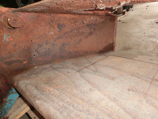
Two practitioners report, that shortening the cylinder base panel by about 2 cm on the outlet side brought about a significant improvement.
Due to this shortening, a further lowering of the chopping unit can then be permitted, so that a smooth feed flow is ensured at all transitions.
If you only have one single chopper unit for your machine, the procurement of two different drum bases could be a solution: one for corn, one for grass.

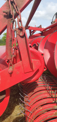
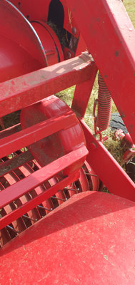
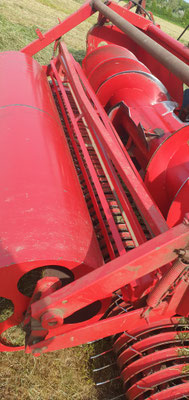
Slide rings upper intake rollers
Due to food residues and rust, these are often no longer movable and can so not fulfill their actual task.
It is recommended to test and restore the smooth running of these rings. If there are very strong traces of wear, these rings must be replaced to prevent further damage (click on the pictures).

Additional roller crop press on PU 3000
In the PU 3000 shown below, a second, smaller roller was installed behind the large hold-down roller in order to further optimize the forage flow.
The arrangement of this roller is adjustable, but not freely movable.


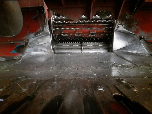
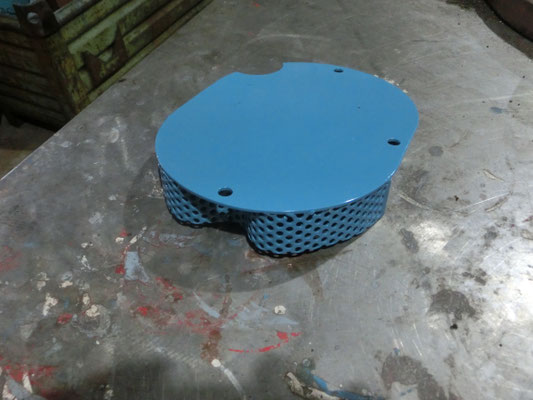
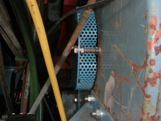
Protective plate with perforated grid at blower SF 6
In one specific case, a rat crawled through the air intake opening on the right-hand side of the blower into the blower or cracker-housing, could not get out and finally starved to death inside.
In order not to have to experience such an unpleasant surprise a second time when cleaning the machine, a perforated plate was welded to the front of the original mudguard in front of the air intake opening. The back was intentionally left open, since a rat cannot climb in here anyway and the air supply to the blower must still be ensured.


Lubrication of main drive chain MG 41, MG 42 and MG 43 Z
The main drive chain of the four-row maize header is very uncomfortable to lubricate while the header is attached to the harvester.
This circumstance can be greatly improved without much effort by attaching a hose to the right side of the rear wall and simply inserting it through a hole in the chain guard.
So you can simply pour oil onto the chain from above while the header is running, without having to get close to the circulating chain.


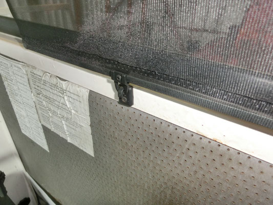
Sun blind rear window SF 6
In the late afternoon hours it gets very hot in the cabin of the SF 6 machines, as a result of strong sunlight coming through the rear window.
An air conditioning system on some machines cools the driver cabin significantly, but the radiant heat on the back is still relatively uncomfortable.
A sun blind, which can be quickly pulled down and rolled up again, offers a significant improvement in comfort.
Such blinds can be found on the Internet for relatively little money and significantly increase driving comfort even on machines without air conditioning.


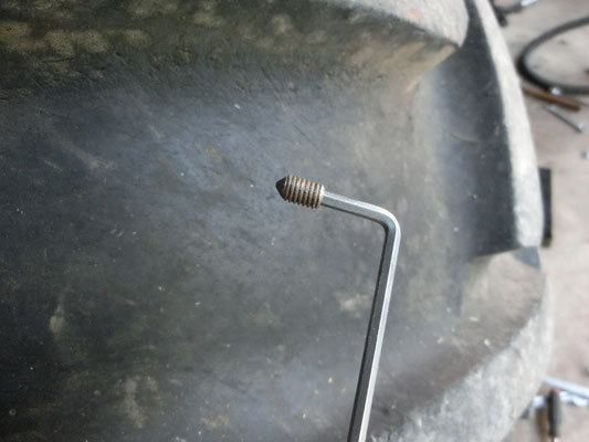
Lubrication of the swing arm of the upper cracker roller
Due to the system, the swing arm for holding the upper cracker roller is almost constantly in motion during chopping.
Since these pivots are not lubricated in their original condition, significant wear occurs over time.
Below we show a modification of the original bolt: This was provided with an off-center 3mm hole into which an M6 grease fitting can be screwed. The lubricating grease can then be pressed into a circumferential groove through a radial outlet hole, which allows the lubricating grease to be distributed all around and thus significantly reduces wear.
For reasons of space, the grease nipple on the left side of the vehicle must be removed again after greasing, otherwise there will be a collision with the tension roller for the cracker roller drive.
After unscrewing, the thread of the grease nipple must be closed with a grub screw.


MG 43Z design-fault in bearing-units of mower discs

During the complete overhaul of an MG 43Z, it was noticed that one bearing was broken in exactly the same place in all four rows.
This was the lower bearing of the mower disc unit, which is spring-loaded.
Although two almost identical ball bearings are installed in each pair of mower discs (2x each with a clamping ring and 2x each with grub screw clamping), different flange housings were used.
And by chance, the bearing in the flange housing in position 22 was defective in all four rows.
Why is that?

The cause was found quite quickly: In a GLCTEY30 bearing housing, this internal circumferential lubrication groove, which supplies the ball bearing with grease, is not present!
The result of this is that although you can press grease into the grease nipple attached to the bearing housing, it immediately migrates back out between the inner wall of the housing and the outer ring of the bearing (see photo on the left).
The bearing remains unlubricated!

When assembling, make sure that the bearing housing used has an internal lubrication groove and that you also install the bearing so that its lubrication hole is aligned with the lubrication groove!
This design error probably affects ALL MG 43s in use that have the new mowing disc bearings installed.
The old version of those mower discs is not affected, if the relevant parts list is to trust.
You can recognize the new mower disc version by the nut attached under the mower discs (see item 15 in the drawing shown above): A nut "M 16" is the new version in question, a nut "M 12" is supposedly not affected old version.