Tips & Tricks
Hydraulic lines of steering system
Warning to all SF 6 drivers: In your own interest, please URGENTLY check the hydraulic lines of the steering system on your machines!
For an initially unidentifiable reason, an SF 5600 had a small oil stain under the left side of the vehicle. The cause was found relatively quickly: corrosion on the hydraulic lines of the steering! A cross-check carried out on a machine of the same construction brought the same result: dirt is collecting between the two steering lines in a hidden spot to the left of the hydraulic oil tank, which cannot be seen without a specific search. At this point, the pipes will obviously rust through at some point during the winter.
We have the affected lines in stock as spare parts!


Clamp shell upper intake rollers

In an individual case, it has happened that the mounting screws on the "arm parallel 04-093 326" have
come loose, the clamp-shell has felt in the chopping drum and there has damaged several knives.
It is therefore recommended to secure the screws with screw adhesive!
Drive shaft MG 41Z/ MG 43Z

Furthermore, it is advisable lubricate this bearing by means of a grease line with grease and to protect it in a steel tube (see top of the picture), so that a simple, safe and fast maintenance is guaranteed.
Scraper smooth roll

Despite very precise adjustment of the smooth roll scraper, it is difficult to avoid that plant residues
deposit below the scraper edge.
These must be removed urgently after the end of the chopping season, since otherwise very strong corrosion would occur. A significant damage to the surface of
the smooth roller would be the logical consequence, which sooner or later would reflect in a very poor intake behavior.
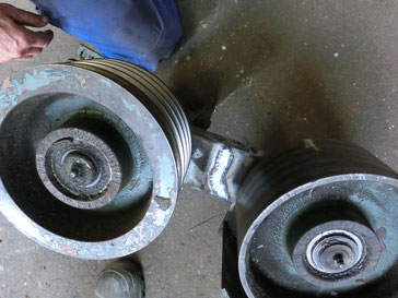
Shear bar locking system for chopping units produced in 1986
The collet chucks for locking the shearbar were dimensioned a little too weak in the chopping units of the first year of production and occasionally could not withstand the pressure of the tension spring. The clamps were bent open a little and the tension spring pushed the lever of the collet apart until the hydraulic cylinder installed for unlocking had reached its maximum stroke. The remaining preload was no longer sufficient to securely fix the shearbar, which sometimes resulted in major machine damage. All owners who use a unit in which the weaker collets are still installed are strongly advised to convert to the newer, reinforced collets! We have a limited number of used, reinforced collets in stock. On the left picture the old collet, on the right the new, reinforced version.


Screws for blades at blower-unit
The "plates" from the ejection blower are fastened in all three types with M12 x 28mm button head
screws. These are not the generally available screws according to DIN 603 or ISO 8677, but a special variant with a shortened square socket. If these screws have to be replaced, only those with a shortened socket approach may be used!
The approaches of the normal button head head screws are too long, which dramatically reduces their clamping force (see photos). Wrong
screws can cause heavy machine damages (click on pictures)!


Corn headers eccentric drive pendulum knife

With the older maize headers of types MG 3 to MG 32 and MG 4 to MG 42, the maize plants are still cut using triangular knives that swing back and forth, which, due to a certain pre-tensioning pressure against their counter-blades, sometimes require a lot of force. If this power requirement is too high, the drive shafts may break or, as in the picture shown, the housings may break. It is recommended to check the preload of the pendulum knives and furthermore to reinforce the housing a little.
Dismounting of a "gib key"

The dismounting of a "gib key" is often associated with greater difficulties. In the case of the
pulleys for driving the crushing rollers, it is not uncommon that this even the left front wheel must be removed.
The chances of success for a quick disassembly are significantly increased if you prepare a sleeve-bushing whose inner diameter corresponds to the outer diameter of each drive
shaft. This sleeve is now slit on the entire length by the width of each "key" to be pulled, so that it sits reasonably stable on the respective drive shaft.
Due to this stable sitting much less energy is lost from the force of a hammer blow, so that one has relatively good chances to solve the respective pulley a piece off the
key. Now you usually get the key out of its seat.
Cracks in cutting cylinder housing upper part
In very rare cases, small cracks appear in the front area of the cutting cylinder cover, which are
probably primarily caused by grass chopping.
It is therefore advisable to check this area on both sides and, if necessary, to weld some small reinforcement plates.
Beware of the metal detector: place the ground-clamp of the welding machine as close as possible to the welding point!


Bearing units of crushing rollers
Since in the spare parts list, the detailed installation position of the sealing rings on the bearings of the crushing rollers
is not clearly recognizable and they are often installed "correct-positioned" so that the injected grease can not escape. As a result, a pressure comes up inside the bearings to such an extent,
that they can get destroyed. The correct installation position of the inner sealing rings, that means the side facing the roller body, must be in theese position that the sealing rings allow the
injected grease to pass and the grease can collect in the cavity behind the bearing housings (see green arrow in the diagram). The mounting position of theese sealing rings must therefore be
"wrong" positioned! Their primary task of theese rings is to prevent the grease from being thrown away from the bearings and to protect the bearings against the ingress of moisture from the
outside.
Since the bearing on the left side of the machine is the "floating bearing", please do not forget the small 8mm spacer ring 04-093 926 when assembling the bearing on the right side in order to
fix the "fixed positioned bearing"!

Hydraulic hoses overload chute
This simple and cheap solution, however, has the problem that the hoses are exposed to constant torsional forces due to the turning of the chute to the left and right. Starting from the tension-free state of the hoses in the transport position of the tower, the angles of rotation of approx. 100 ° to the left and 100 ° to the right must be compensated.
Due to this permanent twisting of the hoses, after decades of use, they could theoretically burst at some point.
By installing two small plug-in couplings in these hoses, this load can be reduced to almost zero, as these couplings can rotate freely when plugged in.
Another great advantage arises when cleaning the machine, because these couplings allow the chute to be dismantled very quickly and without loss of oil.

Cooling water temperature too high
In addition to the generally typical causes such as If there is not enough cooling water in the cooling system, the cooler is not clean, the water pump is worn out, etc., there is another source of interference on the Mengele SF 6 and SF 7: the hydraulic fan drive!
Due to the system, both the hydraulic pump and the oil motor have a certain amount of wear, which is reflected in a fan speed that is too low and the cooling capacity is thus reduced.
The nominal system pressure for both series is max. 180 bar, and a test connection for a manometer is installed in each machine.
If the pressure is now too low, the following causes are known:
1 .: Hydraulic pump and oil motor are worn out, experience has shown that both components have to be replaced after approx. 3,500 to 4,500 operating hours.
2 .: The pressure relief valve (item 6, see drawing) hangs or is defective, both causes have already occurred.
Furthermore: The fan is too close to the cooler! The SF 7 has two holes for attaching the support frame of the fan wheel. The support frame must be fastened in every hole in which the fan is at a greater distance from the cooler! The attachment to the example below is correct (see green arrow)!
-with Volvo engine 2,080 rpm at 140bar;
-with Mercedes engine 1,940 rpm at 160bar;
If the required fan speed is not reached, you can try to temporarily turn the pressure relief valve up a bit.
Attention: After the pump or oil motor has been replaced, please set the correct pressure again!


Support wheels grass header
The time-consuming folding and unfolding of the pick-up gauge wheels for road travel is completely eliminated by this self-construction. Further advantages: The turf is no longer damaged when cornering, the forces on the gauge wheels are reduced significantly and the max. permissible transport width is nevertheless not exceeded.


In case of a possible replica, the corresponding free space of the screw flights to the upper guide tube must be observed
(windings may need to be spared).
Further note: Install the rotation axis of the gauge wheels exactly perpendicularly (= not 90 ° to the longitudinal rocker), then the wheels do not immediately change their running
direction when driving backwards for short periods.
Support wheels grass-header, version no. two
Here is another version of converted support wheels, which also run in front of the pick-up drum and which also do not have to be folded in for road travel.


Chopping Quality in Maize

With increasing resharpening of the knives, the surface on the back of the knife becomes larger (red arrow), while the "open
space" becomes smaller and smaller. This geometry change causes the plant- packet in the infeed-channel to be pressed onto the back of the knife currently in section.
This not only results in an increased power requirement, but it also suffers from the chopped quality, as husks are pulled out of the feed with and thus worsen the chopping result
unnecessarily.
The chopping quality can be significantly improved by increasing the free area (green arrow) of the knives with an angle grinder. The back of the knife is
thus released immediately after the cut and the plant-packet can be transfered easyer in the cutting cylinder again.
Furthermore, the wear on the grindstone is reduced.

Note: Cheap replica knifes are usually sold without this "open space", so we recommend to use only the original "Busatis" knives!
Cracks in oil sumps at Volvo-Penta

In rare cases, cracks in the oil sumps of Volvo Penta engines have become known.
The welding of these cracks is almost impossible, since these oil pans were usually made of double-layered sheet metal and thus infiltrated oil between the two layers.
The cracks all occurred in the area of the oil drain plug, which leads to the consideration of whether they may not be over tightened.
Following consultation with Volvo Penta Germany, the following tightening values were provided:
-TD 71A, TID 71A, TD 121G and TWD 1211P: 80Nm;-TWD 1231 VE 275 EDC and TWD 1231 VE 310 EDC: 60 +/- 15Nm;
Furthermore, the conversion to an oil drain valve (as in the picture above) is generally recommended, as the comfort and time savings clearly justify the investment costs. In addition, the valve must be tightened only once with the investment costs. In addition, the valve must be tightened only once with the correct torque.
For the TD 71A and TID 71A, the valve is compatible with the Hansa-Flex number BOE24-1.5, "Oil drain valve AGM24x1.5".
Price: Approx. 15, - € + VAT
If there is no associated discharge hose on the plant: BOEABLASS3, "Oil drain hose M26x1.5 L = 250". Price: Approx. 6, - € + VAT
According to Volvo Penta, the thread of all the oil sumps mentioned is identical, so this valve should theoretically fit all Mengele- / Case-relevant engines.
Changing knives of cutting cylinder
https://www.youtube.com/watch?v=jBViI-bNeYk&t=81s
Wear knife sharpener year 1986 to incl. 1996
With increasing wear of the grinding roller whose surface is increasingly wavy, which is due to the double wear in the area of the knife overlap. This unfavorable wear pattern can be reduced a little by slightly angling the corners of the blades with an angle grinder (blue arrows), thus reducing the surface to be ground in this area. However, this measure is not a solution to the technical cause!

Parking brake does not release

Due to the long service life over the winter it may rarely happen, that coming from the traction drive transmission
shaft rusts for the operation of the parking brake.
As a driver, you can not determine from the cabin with the utmost certainty whether the brake is really released or not, since the warning light only queries the position of the
hand lever, but not the position of the operating lever for the brake cam.
For safety reasons, therefore, check the smooth running of this gear shaft after longer service lives in your own interest.
An undone handbrake can cause a vehicle fire!

A practicable solution could be the construction shown in the adjacent picture:
Two coil springs pull the operating lever back, while an adjustable stop prevents the over-pulling and thus restoring in the opposite direction.
Axle at crushing roller-unit SF 6-series
The "pin" 03-100 550, which holds the pulley for the power belt of the crushing roller drive on the crushing-unit of the SF 6 series, is ultimately a thin-walled square tube into which two spacer bushings have been welded. Due to these welded-in bushings, the tube is weakened so much at this point that it sometimes cannot withstand the loads that occur and breaks. It is therefore advisable to reinforce the tube on the left and right with a small sheet metal as a precaution (click on the pictures).


Quick-lock for hydraulic cylinder pick-up

In order to prevent the hydraulic cylinder from falling out of the catch bag during the pick-up, two bore holes were used at
manufacturer site.
Provided tabs that are relatively cumbersome to couple. Since the area in question is rather uncomfortable to reach, in the example shown here a
10-steel
plate two catch-hooks burned out, which can be easily swung away when removing the pick-up. If necessary, the "half moons", which are welded on top, serve as
an attack surface for a hammer or a mounting lever if there are problems during dismantling.
Since in such an intervention undoubtedly the paint will pop-off, the "crescents" to avoid rusting made of stainless steel.
Tension lever SF 6
In rare cases it has happened that the tension lever for switching on the main drive of the SF 6 series has
broken.
The problem with this damage is that the steel deforms a bit before it breaks. So you can not simply hold the broken surfaces together during repair welding
and simply weld them, as the two tension rollers would no longer run exactly parallel to one another. A significantly higher power band wear would be the
result.
Restoring accurate parallelism in this case is virtually impossible. All SF 6 owners are advised to reinforce the tension lever 03-087 844 as a precautionary measure (preferably at
the bottom).
From the much more massive lever SF 7 no problems are known in this regard.
Rear support wheels for grass-header

In order to further improve the adaptation of the ground and, above all, to further reduce the damage of the tines into the ground, support wheels were also attached to this pick-up at the rear. The axis is guided in a slot and is height-adjusted by means of two threaded spindles.
Rear support wheel for grass-header, version no. two


Temperature problem Daimler-Benz OM422

With the OM 422 there is
the phenomenon that suddenly they get very hot, but after a short break they immediately reach a normal temperature range.
If you now remove the lid of the cooler and air
bubbles come out of the cooling water, you have probably already found the cause:
A cavitation damage on the outside of a cylinder-liner, with 99%
probability at the front left. In
the cold operating state, the bubbles usually do not occur. Only after a certain warm-up phase, the water begins to simmer.
The
cooling water channel is very narrow at this point in front left, so that flocculates under operating at maximum speed (combine harvesters, shredders, occasionally beet harvester) due to the high
flow velocity of the cooling water oxygen and the bursting of oxygen bubbles in the long term, the cylinder-liner from the outer side wears out. In operation in the medium speed range, as for example in a truck, this problem does not
turn up. With
the Mengele SF 6000, the engine does not need to be removed to replace this liner, the space in the vehicle is sufficient for this repair.
This problem of cavitation damage is not
Mengele-specific, on the Claas 690 or the Claas 116CS, these problems are the same. The OM 442 is not affected by this.
Collision protection chute

Since a collision protection for the chute was unfortunately not available ex works, a self-build solution was installed on this SF 6.The centerpiece of this construction is the "bearing 03-063 824" which is swiveling in the direction of travel on the right by means of lubricated brass bushings. Picture: right view from above.
Picture: right view from below.

On the left side of the machine, a sliding carriage was attached to the appropriate position received a blind hole into which presses a spring-loaded ball. If the chute now collides with any object, the ball is pushed out of its seat and the "bearing", together with the auger, can swing back out of the sprocket of the chute. The release force is adjustable via the spring preload.
Delivery pipes Daimler-Benz V8

The delivery pipes on the Daimler-Benz V8 (OM 422A, OM 442A and OM 442LA) are connected to each other with several rubber-backed sheet metal clamps. Rust can form underneath these metal clips, which permanently weakens the pipes and eventually destroys them.It is therefore advisable to carry out routine checks on these bodies; in the case of damage already incurred, a replacement part price of € 125 / cylinder bank + VAT is to be charged.
Wear crushing rollers

In many machines uneven wear of the crushing rollers is noticeable. In order to alleviate the problem, it is advisable to place obliquely
inward-pointing "scraper bars" on the feed plate. As web height have proven about 10 - 12mm, so that for example as raw material a square 12x12mm can be used.
The beginning of theese guides must be flattened to avoid congestion!
Furthermore, the highest importance is attached to an absolutely reliable attachment of the guides, theese ones in the example opposite were welded and screwed!
When defining the holes for the screws, the space under the feed plate due to the bearing axis of the pulley to be observed, here it can sometimes be very narrow.
With frequent grass use of the machine, it is expedient to keep open the possibility of a rapid expansion of the guides.
Of course, the guides must not be connected to the bottom flap, because otherwise the machine can not be easily cleared out when it´s jamed.
Fuel Injectors on Volvo Penta engines

There seems to be problems with the injectors in the Volvo engines, particularly affected are the two types TWD 1211P and TWD 1231 VE 310 EDC (Mammut 7300 and Case 7400). Often, these nozzles are a bit coloured blue, which allows a conclusion on a
certain temperature issue. Since
several engine damage due to defective nozzles are known, each owner of such a machine in its own interest advised to have the injectors checked regularly! For the TD 121G and the TWD 1231 VE
275 EDC (Mammut 6300 and Case 6900), the problem is not that bad, but a review is recommendable.
Of the relatively robust TD 71A and TID 71A (SF 5200, SF 5600, Mammut 5800), generally no major problems are to be expected, even though in one case the injectors only lasted 300 operating
hours.
Take care when removing the injectors: These are stuck in a
copper-bushing surrounded by cooling water. Never pull the nozzles out of the
cylinder head with force (slide-hammer, etc.)! If you accidentally pull the copper-bushing out of its seat, you
immediately put the entire combustion chamber under water. To avoid
this problem, Volvo has a special tool with the number "6643".
For safety, in addition, the cooling water can be drained, which is also inspired by
Volvo.
A guide to the expansion of the
nozzles is available to us, even the special extractor can be borrowed for a small fee.
Junction box taillights SF 6
A small junction box is attached to the rear right of the main frame of the SF 6, by means of which the rear lights and indicators are supplied with voltage. Some of these junction boxes do not seem to be completely watertight, which can lead to significant corrosion at the contact points. This corrosion must be eliminated, as it can cause a cable fire under certain circumstances (click on the pictures)!


Maize header MG 43Z intake channels

At the inlet of the intake channels, in which the corn is transported to the auger, the beginning of the bottom plate is subject to some wear. The reason is that the floor panel does begin at a distance of about 15cm behind the mower discs. On these 15cm, the corn plants can slide down a piece and are then dragged by the feeder chains over the edge of the bottom plate in the direction of feeder. Sporadically, plants can also remain lying in the canal because their slipped-down part is so long that they bend over and do not slip over the edge.

A remedy here on each channel a simple, obliquely welded sheet metal plate, which acts as a sort of catching slope. The distance to the mower discs is smaller, it no longer hang plants in the channel and the wear of the bottom edge of the sheet is shifted to the catch slope.
Metal Detectors

Many drivers
know the problem: The metal detector is triggered, but nowhere is a piece of metal to be found. The longer you drive
on, the worse it gets. Finally, as an emergency solution, the
detector is then staked out in order to at least be able to finish the today´s job.
Troubleshooting starts at home:
Turn the potentiometer to the right, turn the potentiometer to the left, measure everything, check the mass points, replace the relays, etc.
The
time-consuming search can be reduced acutely if you start with the troubleshooting right at the component, which is the cause of the error in 90% of the cases: The detector himself.
Completely remove the detector from the lower
intake roller and plug it back into the socket of the harvester. Now switch on the ignition, so that the detector is supplied with voltage and is
almost "ready". Dab one or
two fingers a little bit harder (right up to the pain threshold) from the top of the (usually black) potting compound. Below this black mass are four magnets, each affixed with a small
electronics box (see picture).
If one of these magnets triggers due to a vibration caused by your blotch, you have found the error: The gluing of the magnet
with the electronics box has come off!
You can now with gentle force and a lot of patience to carefully remove the potting compound and then resigned to realize that in this case, unfortunately, you can not do
anything. The condition of your detector can be described with just a single word: defective!
According to the manufacturer, the durability of the adhesive has been improved in the meantime, so that the new detectors should theoretically be longer lasting.
New detectors are available on request!
Problematic hydrostatic drive

The hydrostatic drive of a SF 7 showed the following phenomena:
-after engine start Driving only after several minutes possible (noticeable air in the system);
- after automatic venting impeccable performance of the system;
-If the machine is at a standstill with the diesel engine running, the hydrostatic pump will whir with noises;
- audible bubbling in the hydraulic oil tank after switching off the diesel engine;
After a comprehensive troubleshooting (feed valve, flow contol valve, pressure relief valves, feed pump and finally the entire displacement pump replaced) the cause was finally found: In the
supply hose from the hydraulic oil tank to the feed pump, the innermost rubber layer had detached from the fabric.
When removed, only a narrow line was visible in the hose, which stretched over the entire length. At low pressure, this rubber layer dissolves and makes the hose tight, but when the engine is
stopped and the vacuum drops, it almost goes back to its original position. The defect is therefore usually recognizable only at second glance.
In principle, this problem can occur with any vehicle or hydrostatic generator where the pump must suck the oil out of the tank. Some construction machines tension their tanks with 0.5 bar
compressed air to avoid such incidents.
Electric motor knife sharpener up to construction year 1996

Especially after long periods of non-operating of the chopper, it happens in rare cases that the electric motor of the knife sharpener does not work from initially unknown reason. The cause is
rarely a defective electric motor, but usually a rusted pinion shaft. Loosen the cover of the worm gear with gentle force (possibly a chisel) and disassemble the worm gear completely. Grind the
pinion shaft blank again, grease it a little and check its smooth running in the bearing seat.
Now remove the old, mostly anyway resinified grease from the gearbox. Now place the cover plate in the original position of the housing, center the four holes with a 4.0 mm drill bit and then
drill the core holes for the corresponding M4 threads with a 3.3 mm drill bit.
After tapping, ensure complete removal of all chips from the housing, refill with new grease and, once reassembled, your motor is usually ready for use again.
Note: If, in exceptional cases, the electrical system of the motor is actually defective, you can still order this engine from CNH. Via Bosch, the engine is no longer available since 2012, the
last Bosch price was about 270, - €, the Case-IH price is about 320, - €.
Ground level compensation PU 300 and PU 3000

Both series of the 3m Pick-up are equipped with a ground level compensation: The support frame is connected via a thick stub axle with the main frame of the pick-up, the compound is designed as a
plain bearing. To reduce the wear a brass bushing is provided, which is
at some machines not lubricated. This lack of lubrication permanently leads to the destruction of
the brass bushing.
To avoid this
problem, it is strongly recommended to either disassemble this bearing regularly and lubricate with a brush, or to attach a grease nipple. The only possible installation location for this is the underside of the support frame.
Take off the support frame from the pick-up and place a
small hole in the bottom of it, located to the center of the bearing. This must be drilled up to the desired core hole diameter (eg 7.0 mm for a M8x1
thread). The hole is not
only set by the outer frame plate, but of course especially though the bearing tube and the brass bushing, too.
The diameter of the outer through the frame plate leading hole is now to enlarge so far, that the lubricating head of a commercial grease gun can be inserted through this hole (min 16mm).
The
thread (in this case M8x1) is then cut into the bearing tube with a tap, the chips are blown out by means of compressed air and a suitable grease nipple is screwed into it. Finished!

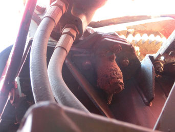
Volvo Penta electronic engine control

The Volvo
Penta TWD 1231 VE 275 EDC and TWD 1231 VE 310 EDC fitted in the Case 6900 and 7400 do not have a mechanical, but an electronic controller for the injection pump.
The
required control unit is located on the engine in the direction of travel front left and is therefore not, as actually provided by Volvo, cooled by the exhaust air of the normally frontally
mounted fan blade.
The
long-term experience shows that these control units can not permanently withstand the ambient temperatures occurring in this area and break due to overheating.
Regardless of
whether you move the control unit away from the engine, install heat shields or air baffles, everything you do is better than the original version. Also additional electric fans are conceivable.
In
the example below, a flexible ventilation hose was simply routed from the engine fan to the control unit as a temporary solution, which causes a noticeable air flow at full
throttle.
If you have another solution for this problem,
it can be published here.

Another way to alleviate this problem is to move the EDC to the left side of the machine so that it is captured by the exhaust air flow from the cooler. However, the fuel lines have to be extended a bit for this, which in principle means an increased fire risk.


Here is another example from a Case 7400 where the EDC has been moved to the rear of the engine and into the exhaust air flow of the radiator. The cooling effect is certainly given here, but there is also a slight disadvantage here from the somewhat longer fuel lines.


Note:
From the purchase of an original spare part with the industrial engine software is strongly discouraged, this helps you in the harvester unfortunately nothing!
In case of damage, please contact us. It may be possible to procure an EDC box with the original software.
Always disconnect the EDC-Unit while welding! !!!
Here is another example of an electrically operated cooling fan:

Colors

If a repainting of your machine is necessary, here you will find a list of the individual shades.
Series SF 6:
-Light blue: Definitely no RAL color, we recommend the "Prosol" paint of the 202-series, color code LM
0232
-Red: RAL 3000 "fire red"
-Silver for Rims: RAL 9006 "White Aluminum"
-White for cabin: RAL 9001 "cream white"
Series SF 7:
-Blue RAL 5018 "Turquoise blue"
-Red RAL 3000 "Fire Red"
-Silver RAL 9006 "white aluminum" (since 1997 also for cabin, see picture)
-White RAL 9001 "cream white" (up to 1996 cabin + front side paneling)
Mercedes-Benz engine block: DB 7350 (eg available from Mipa)
Engine block Volvo-Penta: Color only available as original spare part
This information is provided without guarantee!
Fuse assignment SF 6
In the recent past, there were occasional inquiries regarding the fuse assignment of the SF 6 series.
The following picture shows the overview of a SF 5200 from the year of construction 1988.
Attention: For the model year 1989, there was a facelift, that means the younger years of construction do not necessarily have to agree completely with the old version!

For the sake of completeness, here is the fuse assignment of a Case 6900 from the year 2000:

Bearing units connecting rod Daimler-Benz OM 442LA
The reason for this is, among other things, the size of these bearings, which is somewhat small in relation to the generated engine power. This applies primarily to the OM 442LA, as installed in the SF 7000 and Mammut 7800.
Of the back throttled version OM 442A, as installed in the SF 6600 and Mammut 6800, only a single case is known.
Since a several SF 6000 with engine damage (especially jamed crankshaft) are known or offered for sale, it can be assumed that the series 420 (SF 5500, SF 6000 and SF 6500) is affected by this issue, too.
To avoid a major engine damage, we recommend:
- Changing the connecting rod bearings (and possibly also the crankshaft bearings) latest at 3,500 operating hours!
- Use of motor oil that meets at least the DB specification 228.5 or 228.51!
The possible consequences of a defective rod bearing can be examined on the photo below (click on the picture!).

Addendum: Since an OM 442A with connecting rod bearing damage has now become known again, the recommendation is given to all owners of a machine with a Daimler Benz engine to measure the oil pressures of these engines at least once a year!
As a minimum
pressure, the engine in opertion temperatur, is specified:
- Idle speed 650 rpm: 0.5 bar minimum!
-Nominal speed (not exactly specified): 3.5 bar minimum!
These datas also apply to the motors installed in the Claas-harvesters, the values for the newer OM 502 as
installed in the newer Claas or the Krone-harvesters are comparable.
For the sake of completeness, the datas for the warm Volvo PENTA engines:
-Idle speed (not exactly specified) min. 70 kpa;
- nominal speed (not exactly specified): 300 to 500 kpa;
The "reducing valve" can also be the cause of a low oil pressure in Volvo machines.
Manometer for engine oil pressure in driver's cab
In order to be able to keep an eye on the engine oil pressure while working, an electric oil pressure display was built into the driver´s cab in the following example.
These electric oil pressure displays are known from the "Opel Manta", "Ford Capri" and the "VW Golf GTI" in the '80s.
The advantages are obvious: the separate measurement effort using a workshop pressure gauge is completely eliminated and you are informed about the current oil pressure in every operating and temperature condition.
That gives security!
The following example shows the installation on a DB 442A.


Windscreen wiper blade SF 6

If your SF 6 requires a new wiper blade and you do not know which one fits: Bosch N 100, part no. 3397018199, for example installed in the Neoplan Clubliner from 10.81 to 09. 95 or in the Iveco EuroClass from 01. 93 to 11. 2002.
Although the wiper blade has a 8mm-hole and the wiper arm of the harvester only a 6mm, this is not a problem at all.If you really want to have it 100%, you have to turn two smaller reduction-bushings.
SF 6 with Claas RU 450
There are a few machines from the SF-6 series that drive a Claas RU 450 for maize harvest.
In principle this is possible, but this header is so heavy that the machine has to be reinforced in a few places.
Among other things, this applies to the lifting pins on the chopping unit, which are used to accommodate the harvesting attachments.
In the original version, these were simply welded to a 20mm-thick batten plate, which was sufficient for all harvesting attachments common at the time.
The enormous weight of the RU 450 exerts such a great force on these pins and the frame plate that they can break if there are strong force-impacts while
driving.
Therefore, on all SF 6 units that are to carry a RU 450, an additional outer support plate must be retrofitted and the outer hexbolt must be changed to size M16 (click on
the photos)!
A photo of the required reinforcement of the main frame follows later.


Copping unit frame cylinder mountings

Due to the design, the area between the drum base and the inlet plate of the crushing channel is not 100% sealed, so that
especially when the corn is still very green, a fine slurry drips down onto the frame of the aggregate and also the piston rods of the rear aggregate cylinder.
The acid contained in this pulp can corrode the piston rods, damaged gaskets are the logical consequence.

By attaching a cover plate, this problem can be avoided in a very simple manner. It is best to take a
sheet of stainless steel, then the rust has practically no chance.
This recommendation applies only to the older aggregats, the later ones do have here anyway a steel plate welded by the manufacturer.
Differential gear bushings
The attachment of the two small bevel gears in the differential gear was simply solved by means of a 30-shaft, which is hammered into the differential carrier without play and secured by means of
two roll pins. As sliding bearing a small brass sleeve was pressed into the bevel gears, which should turn as free of play on the bearing shaft. This sliding bearing turns out slowly during the
operating hours, which entails an acute threat to the complete differential. The background: If the play of this bearing exceeds the critical level, it can happen that while the "cornering"
between bevel and ring gear suddenly stands "tooth on tooth". If this happens at very slow speeds (eg when parking in the machine hall), then suddenly and without immediately recognizable reason,
the hydrostat will go to overpressure. However, if this happens during the sweeping turn on the headland, it may be that it cracks the differential cage completely apart!
A first sign is always when you feel a slight play during a load change of the drive train (ie from load to push drive or vice versa).
Experience has shown that this repair is urgently recommended as a precautionary measure starting from the latest 3,500 operating hours.
This applies to all machines that have installed this Claas transmission: Mengele SF, Mengele Mammut, Claas Dominator, Claas Mega, Claas CS, Claas Jaguar 600 series, Case Mammut, Case CF combine, etc.)

In the
picture above you can see the individual parts of this bearing: The bearing shaft (about 170, - € + VAT), the two bearing bushes (about 47, - € + VAT), the bevel gears and the spacer
sleeve. The sleeves shown in the photo had more than a millimeter of "play"
on the shaft. This has also been reflected on the
damaged end faces of the spacer tube, as seen in the photo.
If you get new original Claas
bushings, it may happen that they are even a little too small for the new shaft. Here, some Claas workshops lapidary the hint
given that you have to make this fit with a corresponding reamer suitable. The widening
by means of sandpaper is in principle also, but is very tedious.
In the specific case, the problem was solved as follows: Two bushings made of gunmetal on the existing lathe itself and adapted to the shaft diameter and as additional security, the bushings were
glued with "Loctite 648" in the bevel gears. Material costs: 15, - €!
A few more mounting tips:
-
In order to
remove the "brake flange" you need a pin wrench (Allen key) with a key width of 7mm.
- For the disassembly of this "brake flange" you often need a special puller, but you can make yourself without much effort. Alternatively, you can borrow ours for a small fee.
Since the "brake plate flange" is
now removed anyway, it is recommended to replace the two shaft seals 48x72x12mm.
- The differential carrier does not need to be completely removed, it can be disassembled in the gearbox housing and unfolded so far that you can take out the bevel gears and the spacer sleeve with slim fingers.
The bearing sleeves have the dimensions Do34xDi30xL32mm
- Should a brake pipe fitting become "round" when loosening it: Simply pinch the pipe as close as possible to the fitting. Many car repair shops have a device with which you can re-flange a brake pipe when it is installed (do not forget the new fitting to put on before)
- Since you have to remove the gearbox anyway, it is recommended to check the ease of the handbrake and the storage of the operating lever evl. to grease.
Cutting cylinder scraper

It happens relatively frequently that forage deposit in the gap between the drum housing and the side of the cutting
cylinder. These deposits not only increase the power requirement, but can also extremely wear the lateral end plates of the cylinder. In extreme cases,
even a machine fire can be triggered!
Attaching side scraper bars reliably prevents all these problems.
It is important that one attaches the strips in an outwardly repellent position and that you weld two strips with exactly the same weight exactly in opposite position, to avoid an
imbalance of the cylinder.